Territory is understood as a series of nested scales from the local, to the regional to the global.
– Lola Sheppard | From Site to Territory | 2013
Tsunehisa Kimura | Visual Scandals: Scale |
Landform Building | 2008
DEFINITIONS OF TERRITORY| From Site to Territory
Layered Territory: stratifies its environment into a series of individual layers and systems.
Networked Territory: conceives of context as the subject and product of multiple intersecting networks of human and natural ecologies.
Epigenetic Territory: one in which forces, data and information are continuously scripting its performance.
FOR FRIDAY 10.16 | ORIENTING
Your drawings/collages implement the first principle of CENTERING on the SDSU Campus as well as in the Oceti Sakowin Territory. Through CENTERING, you have begun to establish a narrative about site and territory through the present campus layout, historical events, origins, capitals, etc. By Friday 10.16 you should have a clear idea of where your campus center is located.
1- Using Google Earth (
https://www.google.com/earth/), save your SDSU Campus CENTER, the capitals of the sixteen (16) US Oceti Sakowin reservations as well as the three (3) Oceti Sakowin centers you chose in “My Places” (20 places in all).
2- Using the path tool, draw a line from the SDSU Campus CENTER to the nineteen (19) locations. Save these paths. To be more accurate, you may use GIS coordinates.
3- Email me an aerial shot of these ORIENTATIONS by Friday, 10.16 at 2pm & print it on a letter-sized sheet by Monday 10.19.
using the path tool in Google Earth
FRIDAY 10.16* | DISSECTING THE DRAWING/COLLAGE
*I will be in Chicago this Friday, 10.16. You will use Friday as a work day.
Friday will be used as a day to dissect the drawing/collage through ORIENTING. You will use the day to digitally model the SDSU Campus Center and the three (3) Oceti Sakowin Centers you have chosen.
1- Using Revit or Rhino, digtally model your centers. You are NOT ALLOWED to use Illustrator. Your digital model must use the following layers:
– Orienting Lines (orange): use the path lines from Google Earth
– Topography (green): You can get topo maps from Eros or the
USGS https://eros.usgs.gov/usa
– Present Buildings (blue): use the figure-ground drawing as a basis
– Additional Layers: must be added according to the information in your collage (historic buildings, origins, vegetation, pathways, etc.
digtally modelling the centers in Rhino or Revit
MONDAY 10.19
Digital Models will be due. Print two (2) Axonometric views of your centers and two (2) Perspective views on individual sheets of letter-sized paper. There will be four (4) sheets in all.
– Back up the digital model. We will continue to work with it.
-What are the boundaries of the CENTER? It is better to model more than less (this is an anti-Mies view). The boundaries of the center are not always rectangles.
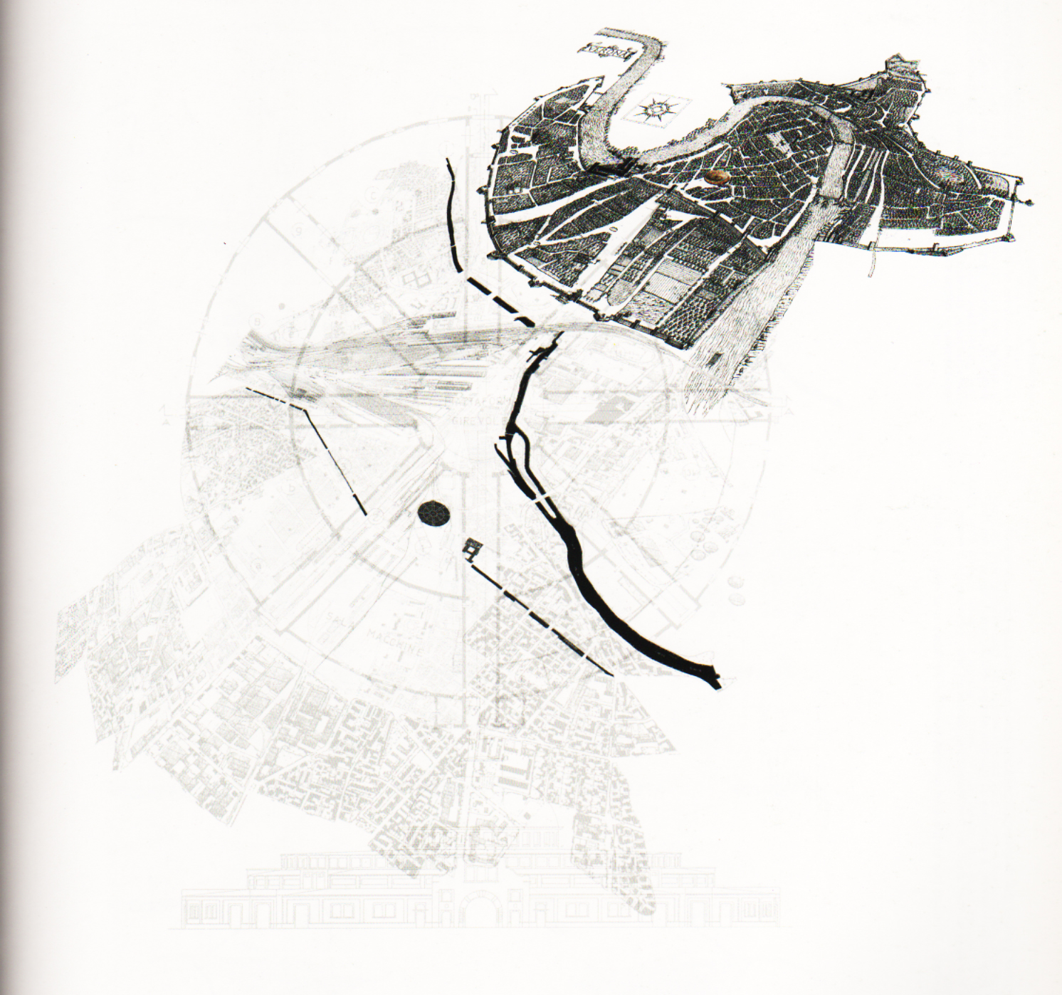
Metis | Mimetic Urbanism – Verona
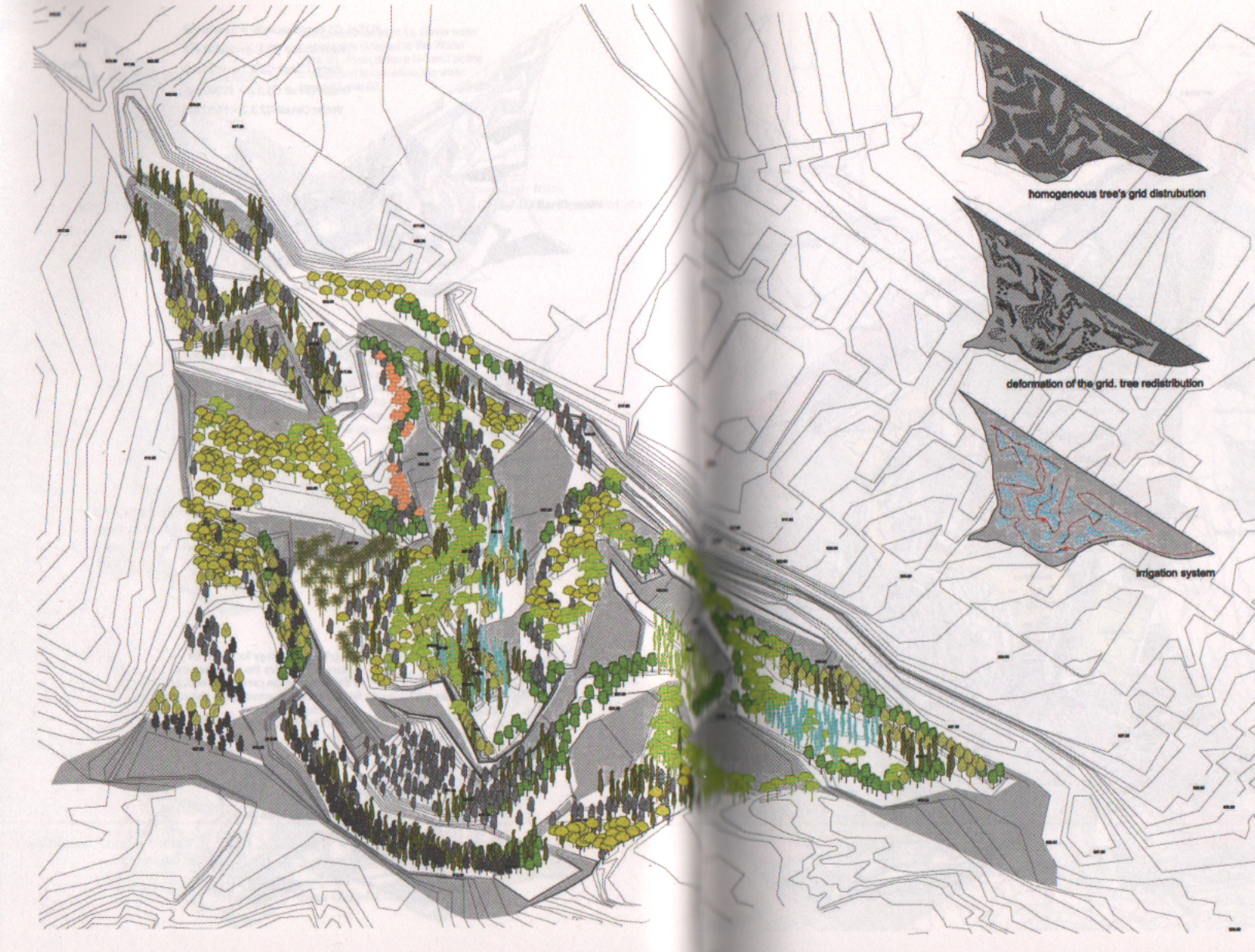
Foreign Office Architects | La Gavia Park in Madrid | 2003
WHERE ARE WE GOING…..
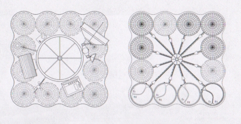
SAA/Stan Allen Architect | Gwanggyo Pier Lakeside Park | 2008
 NEMESTUDIO _ Museum of Lost Volumes
 NEMESTUDIO _ Museum of Lost Volumes
 LIST _ Metropolitan Landscapes
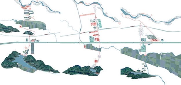
 LIST_ Sportpark, Gent